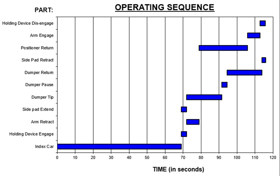
Analysis of the system time cycle can identify the critical path and highlight improvement areas. Examples where improvements can be made often occur during periods of time when:
- no system activity was taking place (these periods could easily be cut)
- multiple pieces of equipment could work simultaneously to shorten the cycle
- equipment was idle or waiting for other equipment to complete an operation.
These scenarios represent potential areas where specific equipment time cycles could be minimized, often by making speed improvements, by performing upgrades, or by installing new equipment.
Common Problems
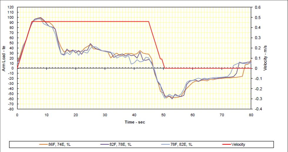
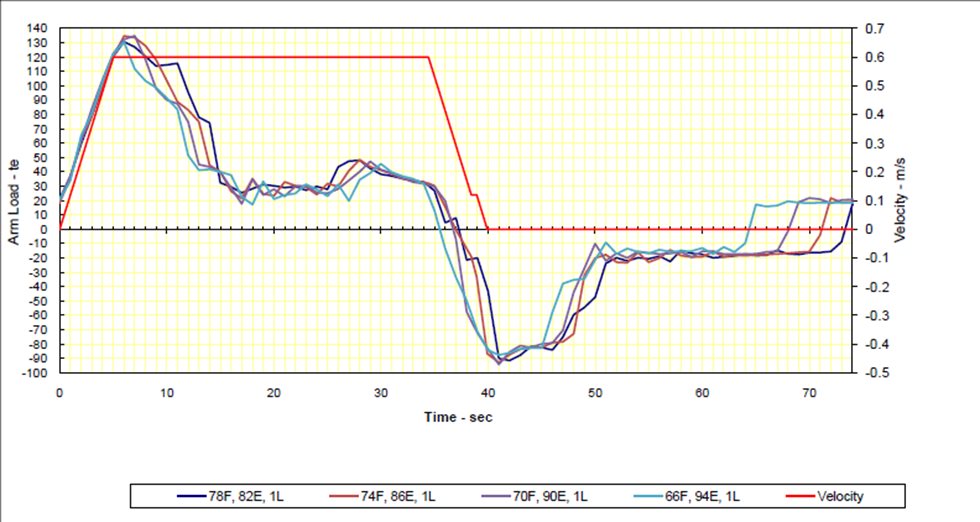
When comparing the operating sequence times in the chart above, inexperienced engineers often assume that the best place to focus their process optimization efforts is on reducing the positioner forward index time since it is the longest individual operation. However, the solution is not always as simple as speeding up the rate of travel of the positioner. Unfortunately, simple changes in velocity, acceleration, and even deceleration can increase the arm load on the positioner, resulting in one or more of the following common problems:
- Increased pinion tooth load and failure of positioner rack and pinions
- Increased rope tension and failure of ropes or sheaves
- Insufficient installed power on the positioner and failure to achieve target speeds
- Excessive arm load and premature arm failure
- Increased overhauling forces and train holding device failure
Recommended Approach
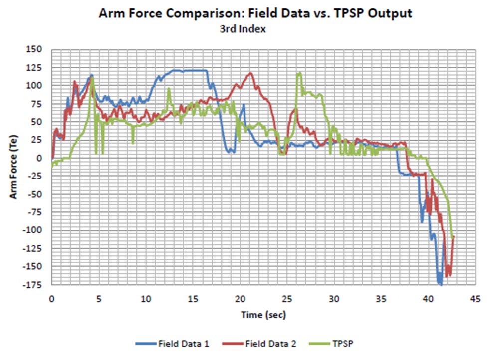
A much better solution uses a train positioner simulation program to calculate the theoretical positioner loads during the indexing cycle. The program models the train as a series of distributed masses connected by non-linear spring couplers. A set of differential equations for motion are solved to predict the positioner arm load including overhauling forces. The program requires a range of inputs including time cycle data—for example, indexing speeds, acceleration, and deceleration ramps—and information on the composition of the train such as the number and gross mass of cars, gross mass of the locomotive engines, and axle friction factors. Track details (grades and curvature) and component mechanical data (coupler draft gear data and haulage drive component inertias) can also be included. The theoretical data can be calibrated to match the actual field conditions by adjusting these inputs.
The chart below shows an example:

