Metso Insights Blog Mining and metals blog Key challenges and technical solutions in e-scrap smelting
Metals refining
Dec 7, 2021

Key challenges and technical solutions in e-scrap smelting

In the first webinar, it was stated that the feasibility of an e-scrap smelting facility depends on multiple factors, and the biggest impact comes from the raw material quality and availability. Since e-scrap contains some difficult elements, proper environmental protection is a must. The emission limits are getting tighter, and also the social license to operate a smelter in the long term is also getting more and more important around the world.
escrap smelter

Click here to access our first webinar, which focuses on the Factors to consider when investing into a new e-Scrap smelter.  This part two discusses the flowsheet process and gas cleaning more in-depth.


Main steps and considerations in setting up a flowsheet for treating e-Scrap

Building a flowsheet for treating e-scrap can be a complex task, but luckily the key steps are quite general.

The first step in e-scrap flowsheet development is to understand the feed. E-scrap can come in many forms, and the feed should have a sufficient description to help us interpret the accompanying analysis.  With sufficient information, we can turn the elemental analysis into a more useful component analysis.

For the purposes of setting up a flowsheet, you can make some assumptions on missing information, but large amounts of unknown material in the feed could lead to a suboptimal solution. Therefore, understanding the feed is key. E-Scrap is a challenging feed source, and its composition and supply are constantly evolving, potentially on a batch-by-batch basis. Ideally, you want a process that has flexibility to accommodate variations in feed. Generally, feeds that are similar will be grouped. Should there be any higher grade material, it may be that it can be fed separately into downstream processes, so as to minimize losses in early processing steps.

The final key piece of information in setting up a flowsheet is the desired product. An existing smelter may be able to feed a black copper into an existing converting process, but a new greenfield site may be looking to produce a refined copper product. Naturally, the more processing required, the more complex the flowsheet can become.


Steps in flowsheet building

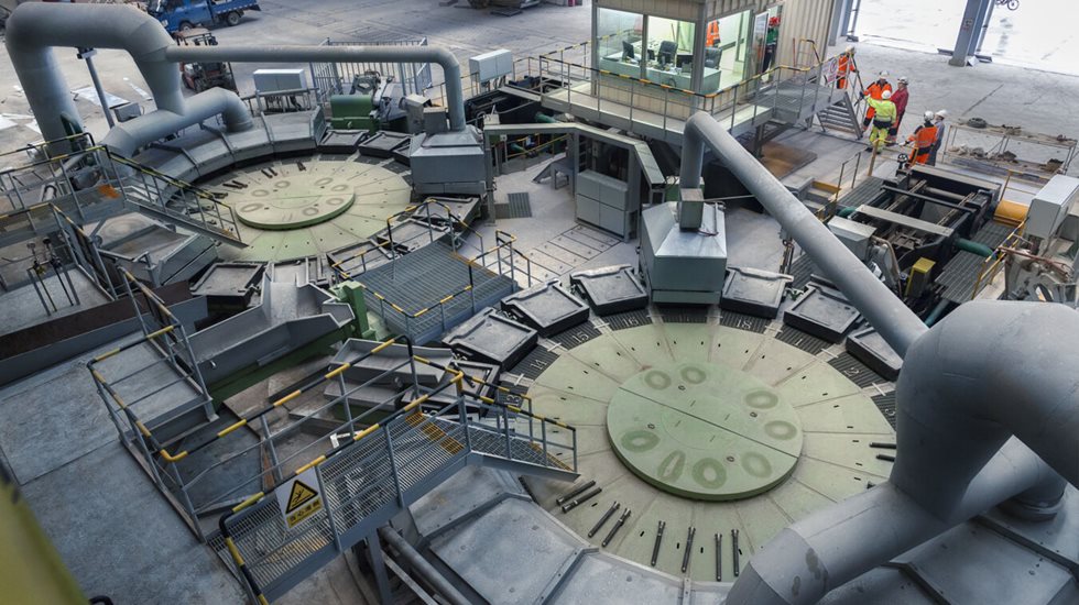
Once we understand our feed, the capacity and desired end product, we can start to set up a flowsheet.  For those of you who attended webinar 1 in the series, we discussed two key Metso Outotec technologies for smelting of eScrap - the Ausmelt process and the Kaldo process. Each has particular strengths, so the best unit can be applied on a case-by-case basis.
escrap flowsheet

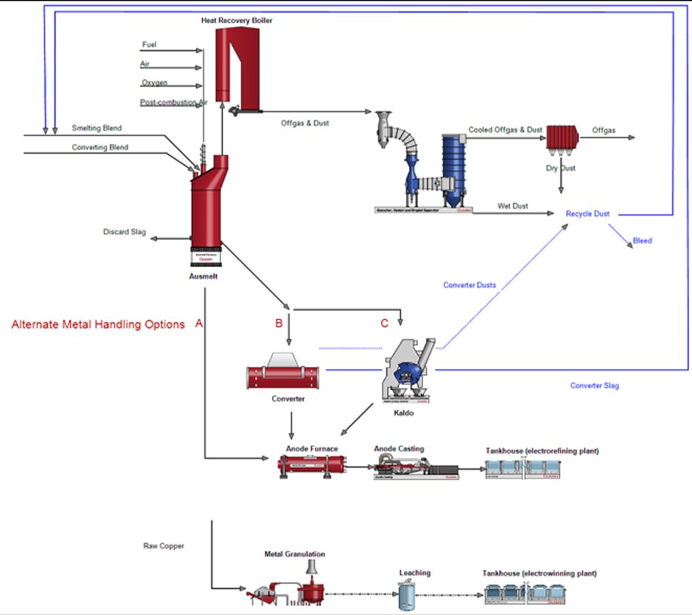
Figure 1 (above) shows a simplified flowsheet developed using HSC Chemistry Flowsheet Simulation software (using an Ausmelt furnace as the primary smelting vessel). The Ausmelt furnace in this example

can be operated in either a continuous process or in a batch wise multi-stage process. Depending on the metal product we want and the overall feed compositions and capacities, we can produce either a black copper, suitable for converting in a converter such an existing PSC or in a purpose built Kaldo furnace.

The raw copper produced from the converters can then be sent to the anode furnace prior to casting and then electrorefining. Alternatively, the Ausmelt furnace could operate in a multi-stage approach, with a smelting stage to produce a black copper and a discard slag.  The black copper is retained in the furnace for the subsequent converting stage to produce a raw copper for further refining. Whether the converting is done in the Ausmelt or a dedicated converting furnace, the feed stock may be distributed to send appropriate higher grade material to the converting stage, or converting furnace.

It is important that we also include offgas handling as the plastics and halides associated with eScrap can present challenges, and thus must be treated appropriately. Figures 1 shows the basic offgas collection equipment, but this can involve several additional units.

The flowsheet will start with the main equipment, but can be expanded from the main furnaces and offgas treatment to include more downstream equipment (for example waste water treatment and beyond). The complexity will depend on the purpose of the flowsheet development.

For all smelting and converting processes, you need to consider the appropriate operating conditions, particularly temperature, oxygen partial pressure and slag chemistry. The temperature should be enough to maintain molten and fluid products. If the temperature is too high, there is a risk of increased wear on refractory and equipment. The chosen slag chemistry will dictate the minimum suitable operating temperature.

Choosing the right oxygen partial pressure in the system will reflect the degree of oxidation and affect the element distribution between gas, slag and metal. As an example, converting has a higher oxygen partial pressure than smelting and produces a cleaner copper product, but more copper goes to the slag.

Recycle streams become an important consideration in flowsheet development. You want to maximize recoveries but also need to have appropriate bleeds from the system. The key recycles here are dust and fume from all the furnaces, as well as converter slag. The dust/fume will contain some feed carryover which will contain copper that we want, but it will also contain some undesired elements, particularly the volatile elements such as lead, zinc and halides. The processing of these recycles will require careful consideration to ensure there is a sufficient outlet, or bleed, for the undesirable components.


Process modelling

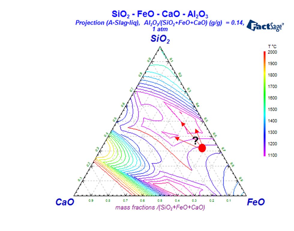
With a pyrometallurgical process, the slag composition will be very important, especially for a TSL furnace where we are injecting gases through a submerged lance. Since the slag must be suitably fluid, fluxing strategies need to be considered. Typically, you want to keep the fluxing to a minimum in order to achieve a suitable viscosity and melting point. Increased fluxing will result in more slag which can lead to increased metal losses to the discard slag, and an associated penalty with regards to energy input.

escrap diagram

This simple phase diagram indicates where a natural feed blend may start (in this case, based on the analyses of the escrap presented earlier), and the directions the slag composition may move in upon fluxing. The slag properties - combined with metal recoveries - will drive the fluxing choices necessary for the process, and these target conditions will not always be the same. Regarding the nature of the feed, there is no one fluxing target. It will be reviewed for each case, and will be a balance between all the competing factors.

Information for modelling of the process steps is obtained from a variety of sources: HSC Chemistry, MTDATA, FactSage, plant data, pilot plant data, laboratory data and literature.

This information needs to be interpreted for the specific process – no two systems are identical. How an element behaves in one furnace may be different to how it behaves in a different type of furnace. Volatile components (such as Pb, Zn, Sb, As, Cd, etc) will usually be the most challenging as the dust and offgas is constantly being removed from the system and this will influence the levels in the metal and slag, and hence equilibrium values.


Key challenges in process modelling

A key challenge in e-Scrap smelting is the aluminum content of the feed, as this is often associated with heatsinks. This aluminium will report to the slag as alumina. Generally, higher alumina in the slags will raise the slag melting point but will have a bigger impact on the slag viscosity when it is molten. Viscous slags are more challenging to treat and handle. Ideally, pre-sorting can remove the majority of any aluminum content, but the amount in the feed will influence the fluxing choices and even the equipment choice (such as Kaldo’s ability to deal with more problematic slags).

The other key challenge in dealing with e-Scrap in smelting is the plastics in the feed. This comes in many forms, such as PVC, Epoxy and more. These present hydrocarbons (which will combust), as well as containing halides. The combustion of these plastics can be beneficial as an energy source to the process. However, depending on the equipment choice, this may provide some primary energy input to help melt the feed and maintain the slag and metal temperature. The component of the plastic feed not utilized directly in the bath will present for post combustion and energy recovery in the heat recovery boiler. With high temperatures possible in the top of the furnace, an intense furnace cooling arrangement would be appropriate. This can include the boiler extending down into the top of the furnace.

The offgas cooling also needs consideration, as the combustion of the plastics can lead to formation of dioxin and furans as the offgas cools. Appropriate equipment needs to be selected to avoid this, requiring the offgas to be rapidly quenched through the formation temperature zone. In this case, the boiler will not cool the offgas fully, but will be combined with a gas cooler for rapid quenching.

Given the variability of e-Scrap, there are always unique issues that need to be addressed in the flowsheet. No one solution fits all, so a tailored solution is required for each situation.

The keys to setting up a flowsheet starts with understanding the feed, understanding the thermodynamics and understanding the equipment.
Ross Andrews, Process Design Manager - TSL Smelting Technology

Metallurgical testing

Current thermodynamical databases cover the most important elements in primary copper smelting pretty well. However, elements like tin and lead that are relevant to e-scrap processing do not have enough data. Therefore, experimental testing may be needed to determine their distribution coefficients under process conditions of interest.

If the amount of test material is limited or does not exist, you have to rely on laboratory scale experiments (synthetic or doped slags can be prepared, if needed). Reduction experiments can then be done to find out how the distribution coefficients change as a function of a certain process parameter.

If you have a sufficient amount of raw material available, you can go to pilot scale. In Metso Outotec, we have both pilot-scale TSL and Kaldo furnaces available. Similarly, distribution coefficients can be determined but also estimates on coke consumption in reduction or energy balance can be provided. This information can be used in modelling and in scale-up.

We use process modelling, thermodynamical modelling and experimental testing to develop an optimized flowsheet for each case. Thankfully, we have worked with these topics for a long time and have the data and results already available. We do not have to start from scratch. We know the metallurgy and are here for you.
Mari Lindgren, Director - Research and Development

Overcoming e-Scrap challenges: Slag quality

Controlling the slag quality and physical properties during e-scrap smelting is a key to a successful operation.

  • During smelting stage, the same slag system for Ausmelt TSL and Kaldo is used.

  • Higher demands of the slag quality in the Ausmelt as a fluid slag is a must, in Kaldo, higher slag viscosity can be tolerated.

  • Fe-SiO2-CaO-Al2O3 slag system for smelting and FeO-SiO2 for converting

  • Different slag handling setup for different cases.

    • Slag reduction or not in the furnace or separate furnace

    • Converting slag to remain in furnace into the next cycle is possible


Goals for dealing with slags:

  • Dilution of impurities but to a certain level (not too much slag, not too little)

  • Slag defining element can vary and most probably will change over time. Today we see that Al2O3 is the slag determining component.

  • One target is to use as little flux as possible. Letting the raw material mix do the fluxing by utilizing SiO2 from circuit bords and iron from electrical motors fraction with Fe/Cu or other Fe-Cu fractions etc.

  • A good slag metal separation for good Cu and PM recovery


The challenges with dealing with slags are:

  • Unknown or varying feed composition or huge stockpile for pre-determined element assays is one trade off to consider.

  • Keeping a low viscosity slag at reasonable temperatures (1250°C) for minimizing PM losses, refractory wear, risk of organic enclosures giving poor combustion stability resulting in lower feed-rate


Overcoming e-Scrap challenges: Impurities

Another main challenge during e-scrap smelting is the handling of various impurity elements.

Working environment: One category of element that is the ones that you don’t want to get into your smelting system that is a working environment hazard. This includes beryllium and radioactive elements. Also, e-scrap with mercury components should be avoided. However, there will inevitably be residues of mercury in the e-scrap to smelting. Beryllium and mercury components need to be detected manually and radioactive elements are avoided by scanning all incoming materials for radioactivity. Lithium batteries should also be avoided, as they can be a fire hazard during crushing and storing e-scrap.

Circulation and by-products: Another category of elements is the ones that could be potential circulating loads and by-products in the e-scrap smelting process such as lead, tin, zinc and nickel. These elements could be handles and treated to by-products if there are enough amounts of them, or be diluted into the copper product and slag. One example is lead that will distribute to the dust and black copper phase.

If all the dust is circulated, the lead will accumulate in the system - especially the converting slag. With enough lead, a separate slag reduction stage can be motivated to produce a lead alloy. If there is not enough, the lead can be bled out with the smelting slag, copper product or dust as options.

Slag elements: Slag handling is a key and should be planned carefully during feed mixing and monitored during operation. Elements like Si, Cr,,Al Mg and Fe are typical slag elements in the e-scrap smelting process. Adjustment of slag composition can be needed.

Cu impurities: Traditional Cu impurity elements like Bi and Sb have had a declining trend and are getting less attention in e-scrap smelting. These elements can be difficult to remove during converting and need to be diluted.

Environmental challenges: Elements such as Cl, Br and Hg are important to control. Read more on this in the gas cleaning section below.


Gas cleaning flowsheet development

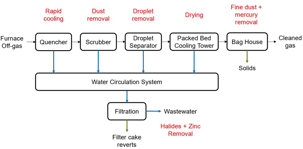
  1. The development of the gas cleaning flowsheet always starts by determining the design basis. This is potentially the most important step, since the design basis will eventually determine the equipment sizing and the water and mass balance. One of the most important aspect of the gas design basis is the contents of halides in addition to metals like zinc, lead, and tin. Halides will influence the necessary water bleed amount, and metals with low vapor pressure will influence the heat balance and dust amount of the gas.

  2. The next step is to study the environmental performance requirements and discuss with the client if there are any preferences of how to handle by-product and waste streams

  3. Then, a process model will be made with professional modeling tools like for example HSC. The modeling tools will simulate the process and calculate water, mass, and heat balance. By-products can be directly reverted to the furnace and thus closing the loop of circulating loads of certain elements.

  4. Finally, when process modelling is ready - the equipment sizing can be made.

gas cleaning process

Gas cleaning main process steps

The only viable solution for the treatment of gases from electronic scrap smelting is wet-dry gas cleaning. The wet gas cleaning system ensures minimal formation of harmful dioxins, efficient dust removal and halides removal.

The furnace off-gas have been incinerated to ensure no flammable hydrocarbons, carbon monoxide or hydrogen gas is present:

  1. The quencher ensures the gas is rapidly cooled, minimizing the amount of dioxins formed. Dioxins are naturally formed when organic material burnt with halides present between 200 to 450 hundred degrees centigrade. With the quencher, the gas is cooled fast from up to 1000 degrees to below 100 degrees celsius. The formation of dioxins is a common problem for waste incinerators.

  2. The Conturi-scrubber effectively separates the dust present in the gas utilizing the pressure drop. Due to the nature of e-scrap, a lot of dust is formed during the smelting process.

  3. The droplet separator removes small droplets still present in the gas after the scrubber, which is necessary for removal of the dust containing droplets prior to the packed bed cooling tower.

  4. The packed bed cooling tower will cool the gas by direct contact with cold water. The water is recirculated and cooled with heat exchangers. Since the gas temperature decreases, vaporous water will condensate thus reducing the gas amount lower the risk for downstream condensation.

  5. The final gas cleaning step, the bag filter, separates fine dust. Additives injection is possible, and the polishing bag filter will catch sulfur, mercury, and dioxins if present.

The water bleed will contain halides and dissolved metals due to the acidic nature of the system. Zinc can be separated from the system this way which is required. Zinc cannot be circulated back to the furnace since it would form a closed loop. Zinc and other dissolved metals will be handled in the wastewater treatment.


Gas cleaning options

In addition to the main process, it is also possible and sometimes required to add additional systems.

For the Kaldo furnace, it is necessary to include a ventilation system. The whole furnace is covered with a casing that maintains a small negative pressure around the furnace. Since there is a risk of some un-combusted material in the ventilation gas, the gas is first led into a spark cyclone that will censure no burning material ends up in the following ventilation bag filter.

In the post-combustion duct or gas uptake before the quencher it is possible to install a waste heat boiler that enables the production of steam. Precipitation of metals directly in the water circulation system is possible which can in some instances be preferred instead of selective precipitation in the water treatment plant (for example, if existing water treatment plant has limited capacity).

The filter cake contains valuable metals. It is possible to revert this to the furnace or it can be further treated with hydrometallurgy or dried into water free dust for example.

There are many different solutions for NOx removal and the two viable options for this gas cleaning system is either by oxidation and scrubbing or selective catalytic reduction (SCR) in the bag filter after the packed bed cooling tower.


In conclusion

It is important to realize that in setting up an e-Scrap smelting process, deep metallurgical knowledge is key. Process modelling complemented by testing is also an important step in the development and future success. Metso Outotec offers complete eScrap solutions built of proven technologies to suit any e-scrap challenge.

Here in Metso Outotec, we have the knowhow and capabilities for the whole flowsheet, from raw materials to refined metals, to support our customer the through the whole lifecycle of a plant.

This has been transcribed from a webinar by Hannes Holmgren, Ross Andrews and Mari Lindgren.

In this interests you or you want further information, view our webinar that focuses on the factors to consider when investing in an e-Scrap smelter.

This article is part of our Smelting Newsletter Issue 2/2021. Visit the issue front page for all articles and greetings from Lauri Närhi, Head of Sales - Smelting.

Watch eScrap smelting webinars

Webinar
{{ title }} {{ ingress }}
Metals refining
Webinar
{{ title }} {{ ingress }}
Metals refining
Metals refining